
Thickness of a Flex Circuit
The copper thickness of a flex circuit is an important factor that affects electrical performance, reliability and cost. It is also a major design variable that can influence the maximum allowed bending radius. The typical thickness of a flex circuit is between 2 and 8 layers, with the number of layers influencing the amount of stiffening required. When the layers increase, the PCB becomes more rigid and less flexible. This increases the pressure on joints and leads to more stress accumulating in those areas.
It is important to design a flex circuit with the appropriate copper thickness for its intended environment and use. Copper thickness directly impacts current carrying capacity, thermal performance and impedance. These are critical factors for a reliable flex circuit that can be used in harsh environments where it is subjected to heat, humidity, chemicals, shock and vibration.
While it is common for a flexible circuit to be made with a glass-epoxy or a glass fiber core, flex circuits can also be manufactured using a thin, flexible dielectric film such as PI (polyimide). These films are often laminated with a solder mask and a coverlay that insulates the conductors and protects them from corrosion and damage.
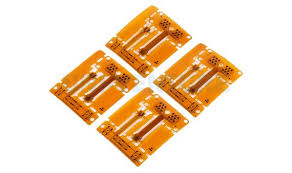
What is the Typical Thickness of a Flex Circuit?
A flex circuit’s copper track width should be kept consistent throughout the length of the traces and at the corners. This will reduce stress on the copper and increase its longevity. Abrupt changes in width can create weak spots that will fatigue and break over time. For this reason, a gradual transition from wide to narrow traces is preferred. The track width should also be tapered down where it ends in a pad or a via. This will help to prevent tears during the manufacturing and assembly process.
When designing a flex circuit, it is advisable to avoid sharp bend angles. They reduce the lifespan of the board and may result in tracing failures. In addition, a flex circuit’s copper tracks should be run perpendicular to the overall bend radius to reduce stress and friction in those areas. Keeping these traces as straight as possible also reduces the chance of failure by minimizing l-beaming, which can cause copper track breakage.
It is also a good idea to keep the area surrounding a flex circuit’s bend free of discontinuities like vias, cut-outs and slits. When these are located at a bend, they can produce stress and cracks that will eventually lead to failure. Adding tabs or anchors to vias can also assist in preventing peeling during the manufacturing process. In addition, utilizing a circular section (relief hole) for end cutouts and slits will help to minimize tearing at those locations. This is a vital part of making a successful flex circuit that meets IPC standards for durability and quality.